LIDAR Basics
Lidar, an acronym of LIght Detection And Ranging is a method for determining ranges by targeting an object or a surface with a laser and measuring the time for the reflected light to return to the receiver. Lidar may operate in a fixed direction (e.g., vertical) or it may scan directions, in a special combination of 3D scanning and laser scanning.SLAMTEC RPLIDAR C1
The Slamtec RPLIDAR C1 is a compact 360° 2D LiDAR. It uses a fusion of triangulation and Direct Time-of-Flight (DTOF) ranging technology to deliver reliable distance measurements up to about 12 meters for well-reflective surfaces, with a typical angular resolution of around 0.72° and a scan rate near 10 Hz. The device samples rapidly (about 5000 Hz) to build detailed planar scans of its surroundings. It’s lightweight and easy to integrate via a TTL UART interface, and supports SDKs as well as middleware such as ROS/ROS2 for development of robot positioning, mapping, and obstacle avoidance systems. Its laser meets Class 1 eye safety standards and it’s suitable for use in home robotics, educational projects, hobby builds, and light commercial robots.
Setup
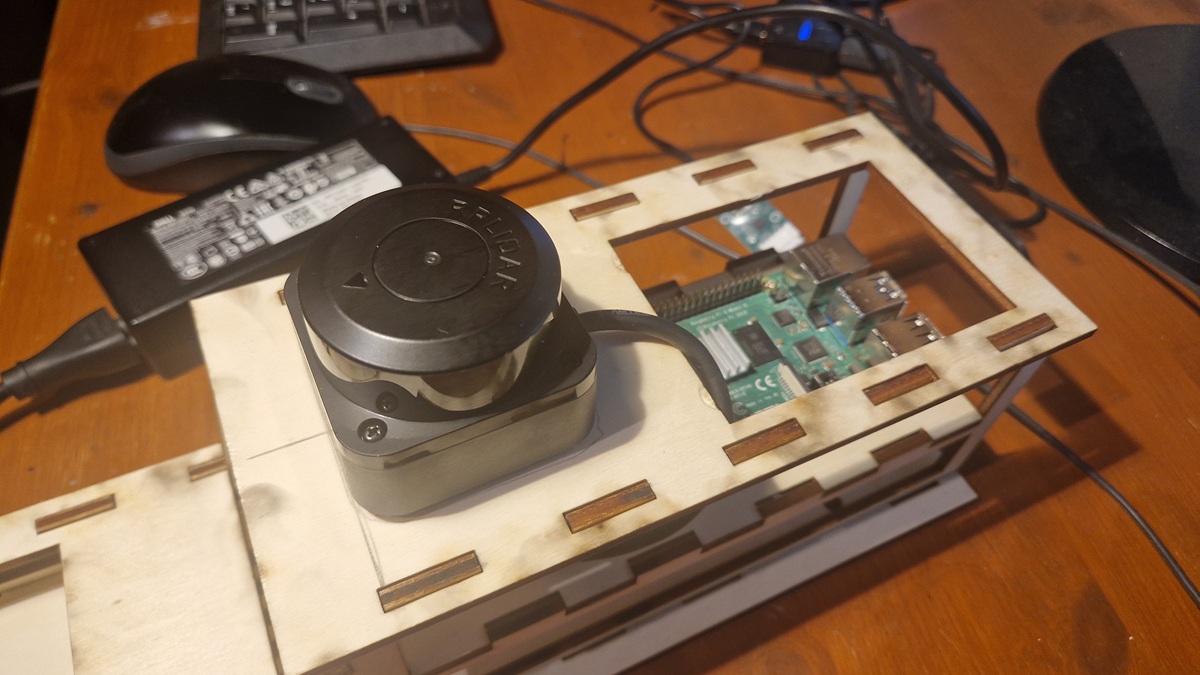
The simplest way to use the RPLIDAR with a Raspberry Pi is to interface through the bundled USB adapter. Connect a USB cable on the Raspberry Pi and then plug the other end into the LIDAR USB adapter board. However, I had the following problem: No matter which library I tried, none of them worked properly.But ultimately it wasn't a problem: I simply queried the data at a low level via the serial interface. But to do that, one needs to take a closer look at the technology and data formats of LiDAR.
The software setup is quick and easy, because you basically only need access to the serial interface.
pip install pyserial
To check if the device is available, you can use the following Pyton script:
import serial.tools.list_ports

ports = serial.tools.list_ports.comports()
for p in ports:
    print(p.device, p.description)
Depending on the operating system, you usually get a tty (Linux) or a COM port (Windows), like:
/dev/ttyUSB0
# or
COM5
Working States and Commands
RPLIDAR has the following 4 major states: Idle, Scanning, Request Processing and the Protection Stop state:
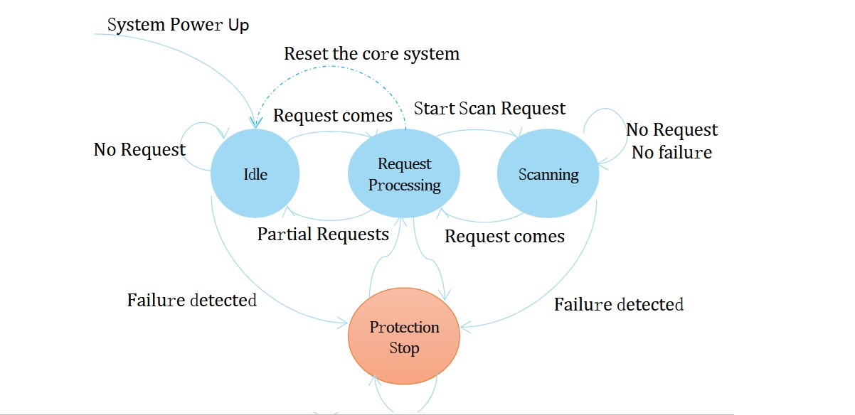
PLIDAR will exit the current scanning state once it receives the Stop (0x25) Request sent by a host system. The laser diode and the measurement system will be disabled and the Idle state will be entered. This request will be ignored when RPLIDAR is in the Idle or Protection Stop state. Since RPLIDAR won’t send response packet for this request, host systems should wait for at least 10 millisecond (ms) before sending another request
Commands can be sent to the LiDAR as follows:
0xA5 = SYNC BYTE (Startbyte for commands)

Command	        Bytes	    Meaning
===============================================
Start Scan      A5 20       Start scanning
Stop            A5 25       Stop scanning
Reset           A5 40       Reset the scan
Get Info        A5 50       Device information
Get Healt       A5 52       Status
Sending Commands with Python
Functions for sending commands in Python could look like this, for example:
def send_cmd(ser, cmd_bytes):
    ser.write(cmd_bytes)
    time.sleep(0.05)

def start_scan(ser):
    send_cmd(ser, b'\xA5\x20')  # START SCAN

def stop_scan(ser):
    send_cmd(ser, b'\xA5\x25')  # STOP

def reset(ser):
    send_cmd(ser, b'\xA5\x40')  # RESET
What's coming back?
Good question! It wasn't easy to find out. But luckily, there's very good documentation for the C1 RPLIDAR that explains the exact structure of the data packet:
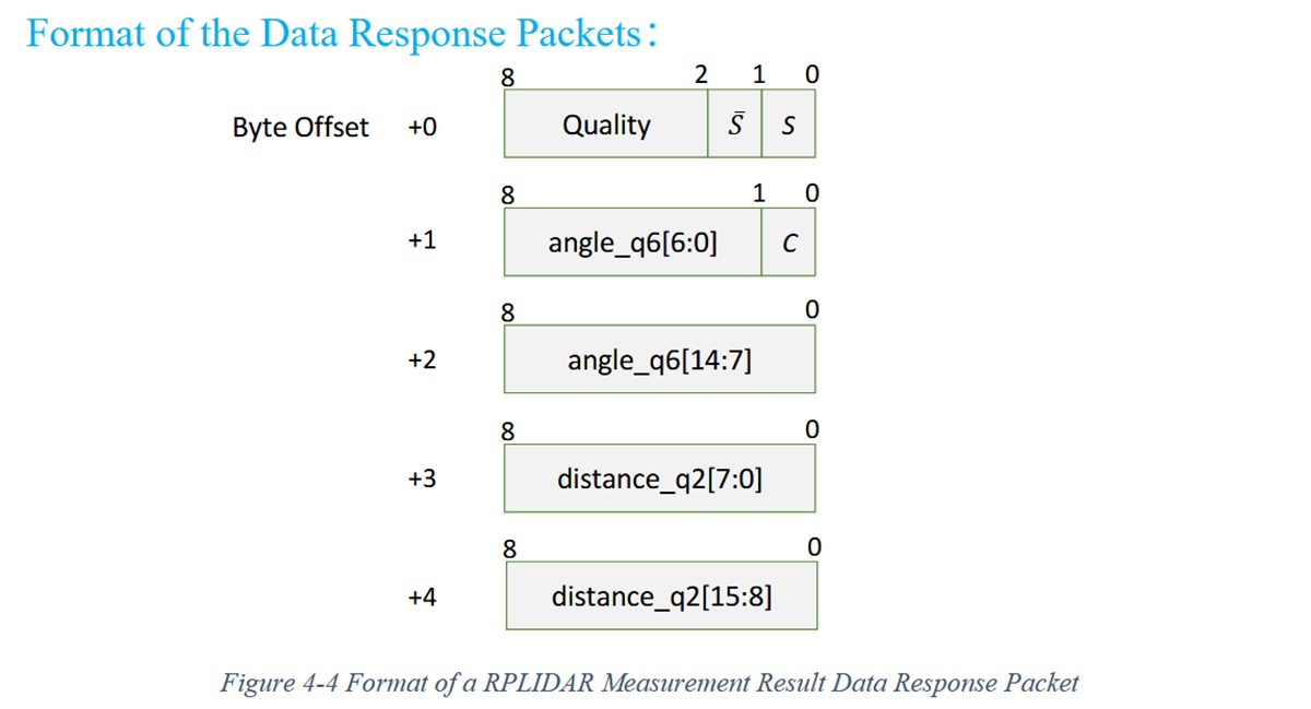
RPLIDAR encapsulates each measurement sample into a data response packet with the format showed in the above figure and send the packet out. Warning: you really need to be careful here! If you look closely at the data, you'll notice that angle and distance each consist of two bytes.
BUT: for the angle, the bit with index 0 is set as a synchronization bit and does not belong to the value.
The 15th bit is not used; the value consists of only 14 bits. This must be taken into account when converting data
with Python.
To obtain the correct value for the quality, you simply need to shift by 2 bits.
angle = ((b1 >> 1) | (b2 << 7)) / 64.0
distance = (b3 | (b4 << 8)) / 4.0  # mm
quality = b0 >> 2
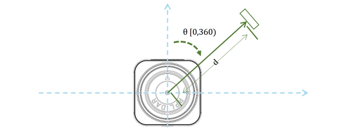
The Coordinate System
To interpret the data correctly, you need to know how to interpret the angles. Good documentation helps with this as well. The geometric definition of the included angle and distance value is shown as below: