Color-Detection with Arduino
The TCS230 is a sensor for color detection. The color to be detected (more precisely: the colored light) is recorded by an 8x8 matrix of photo diodes. An integrated current-frequency converter converts the detected values directly into a square-wave signal, which is proportional to the detected light wave/intensity. The microcontroller connected to the output of the sensor can now evaluate this signal.
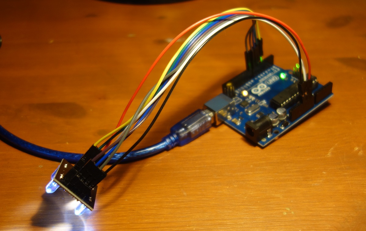
Required parts:
1 x Arduino Uno (or compatible)
1 x Color Sensor TCS 230
8 x jumper cable male - female
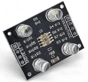
The photo diodes have three different color filters. All photo diodes are connected in parallel and connected to the control PINs S2 and S3, which can be used to select which color is to be detected. The following table shows how to read the PINs in order to detect which color.
S2    S3    Color
------------------
LOW   LOW   red
LOW   HIGH  blau
HIGH  LOW   white (no filter)
HIGH  HIGH  green
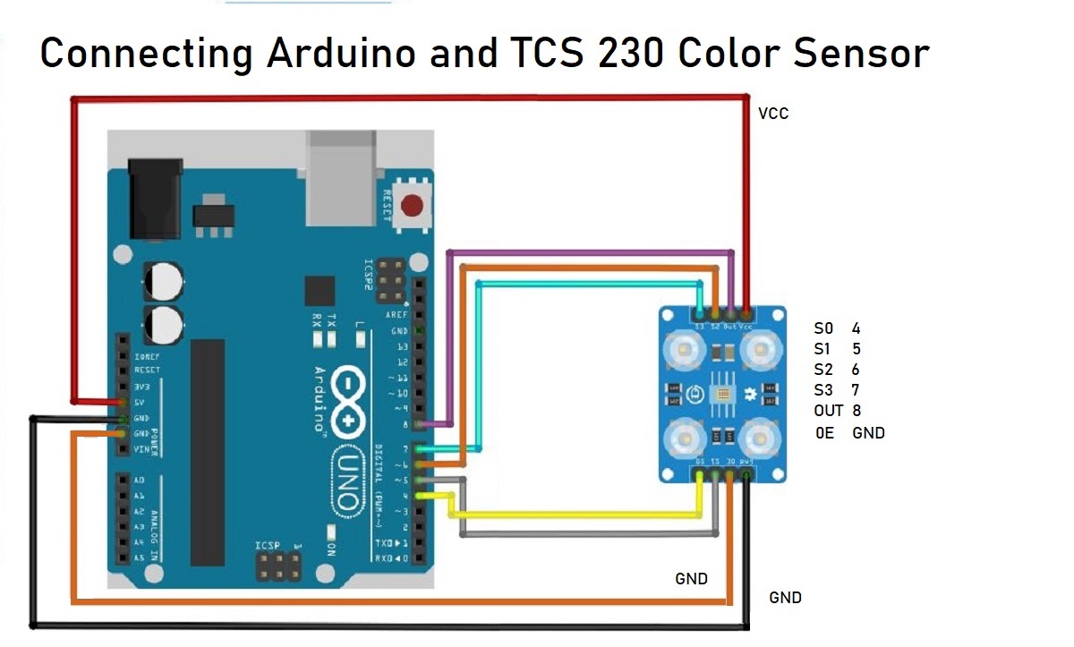
Wiring Diagram for TCS 230 Color - Sensor
Arduino           TCS 230
-------------------------

5V                 VCC
GND                GND
4                  S0
5                  S1
6                  S2
7                  S3
8                  OUT
OE                 GND
The sensor pins S0 and S1 are required to scale the frequency of the output signal. The frequency changes depending on which pin a HIGH or LOW is applied to:
S0     S1     Frequency
------------------------
LOW    LOW    off
LOW    HIGH   2%
HIGH   LOW    20%
HIGH   HIGH   100%
This setting is required because different microcontroller boards process input signals differently. For the Arduino, the scaling should be 20%: Arduino pin 4 should be HIGH and Arduino pin 5 should be LOW.
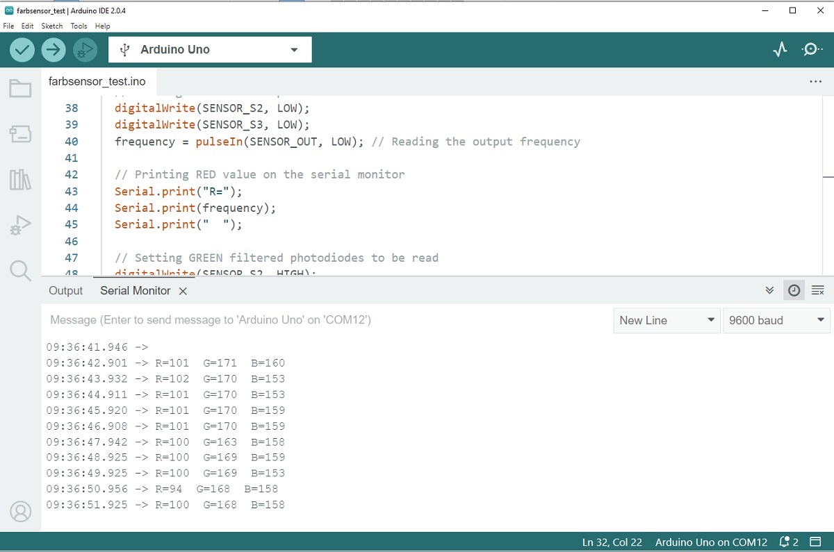
Software for Functional Test
For a test, simply start the program, hold objects with different colors in front of the sensor and read the raw vlaues on the serial monitor.
/* Color Detection Test with TCR 230 - Sensor for Arduino
 * This program does not provide a determined color value but the raw data from the sensor.
 * On the one hand, this serves as a test to see whether the sensor is working.
 * On the other hand, you can use it to output the raw data, which you can later
 * use to implement color recognition via a mapping.
 *
 * (c) Stefan Hager 2024
 */


#define SENSOR_S0 4
#define SENSOR_S1 5
#define SENSOR_S2 6
#define SENSOR_S3 7
#define SENSOR_OUT 8

int frequency = 0;

void setup()
{
  pinMode(SENSOR_S0, OUTPUT);
  pinMode(SENSOR_S1, OUTPUT);
  pinMode(SENSOR_S2, OUTPUT);
  pinMode(SENSOR_S3, OUTPUT);
  pinMode(SENSOR_OUT, INPUT);

  // Setting frequency-scaling to 20%
  digitalWrite(SENSOR_S0, HIGH);
  digitalWrite(SENSOR_S1, LOW);

  Serial.begin(9600);
}

void loop()
{
  // Setting RED filtered photodiodes to be read
  digitalWrite(SENSOR_S2, LOW);
  digitalWrite(SENSOR_S3, LOW);
  frequency = pulseIn(SENSOR_OUT, LOW); // Reading the output frequency

  // Printing RED value on the serial monitor
  Serial.print("R=");
  Serial.print(frequency);
  Serial.print("  ");

  // Setting GREEN filtered photodiodes to be read
  digitalWrite(SENSOR_S2, HIGH);
  digitalWrite(SENSOR_S3, HIGH);
  frequency = pulseIn(SENSOR_OUT, LOW);

  // Printing GREEN value on the serial monitor
  Serial.print("G=");
  Serial.print(frequency);
  Serial.print("  ");

  // Setting BLUE filtered photodiodes to be read
  digitalWrite(SENSOR_S2, LOW);
  digitalWrite(SENSOR_S3, HIGH);
  frequency = pulseIn(SENSOR_OUT, LOW);

  // Printing BLUE value on the serial monitor
  Serial.print("B=");
  Serial.print(frequency);
  Serial.println("  ");
  delay(1000);
}